Hybrid PCB High Frequency 4 Layer Mixed PCB Built on 12mil RO4003C and FR-4
(PCBs are custom-made products, the picture and parameters shown are just for reference)
Introduction
Hello Everyone,
Today, we will discuss a 4-layer high-frequency PCB constructed using 12mil RO4003C combined with FR-4 materials.
This board features a 4-layer structure, which is relatively simple and cost-effective, making it an excellent choice for entering new markets.
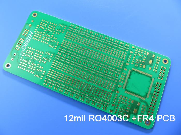
Let’s see today’s first board.
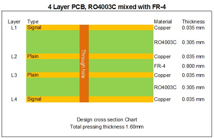
In the stack-up, the first and second layers, as well as the fourth and third layers, consist of a 12mil core of RO4003C. This fixed thickness is crucial for maintaining the electrical length of RF lines on the circuit board. The remaining layers utilize FR-4 materials. The copper weight for both the inner and outer layers is set at 1 ounce.
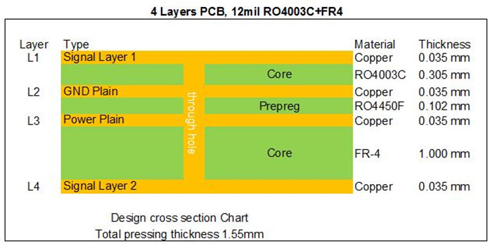
For the second board, the FR-4 is positioned in layers three and four. Depending on actual applications, the thickness of the dielectric material and FR-4 can be adjusted accordingly.
The stack-up consists of layers from 1 to 2 made of the fixed thickness RO4003C core (8mil), which is crucial for maintaining the electrical length of RF lines on the circuit board. The remaining layers utilize FR-4 materials, and all boards feature through holes.
Applications of the 12mil RO4003C Hybrid PCB
The applications for the 12mil RO4003C hybrid PCB are extensive, including:
Applications
Modular oscilloscopes
Antenna combiners
Balanced amplifiers
4G antennas
Advantages of the 12mil RO4003C Hybrid PCB
The benefits of the 12mil RO4003C hybrid PCB are highlighted in the following points:
1)Stable Dielectric Constant: RO4003C maintains a consistent dielectric constant across a wide frequency range, making it an ideal substrate for broadband applications.
2)Reduced Signal Loss: This design minimizes signal loss in high-frequency applications, aligning with the evolving needs of communication technology.
3)Cost Efficiency: Utilizing this hybrid approach can reduce costs compared to stacks made entirely of low-loss materials.
Common Hybrid Material Combinations
Currently, the following mature mixed pressing materials are popular:
RO4350B + FR-4
RO4003C + FR-4
F4B + FR-4
RT/duroid 5880 + RO4350B
RT/duroid 5880 + FR-4
Our PCB Capabilities (Hybrid Design)
We also offer blind via boards, buried via boards, and HDI boards. All PCBs produced by our company undergo rigorous testing, including AOI inspection, open and short circuit testing, solderability testing, and thermal stress testing at 288°C to ensure the highest quality before shipment.
Thank you for reading. Please feel free to contact us for your RF PCB inquiries.
Appendix: Data Sheet of RO4003C
RO4003C Typical Value |
|||||
Property |
RO4003C |
Direction |
Units |
Condition |
Test Method |
Dielectric Constant,εProcess |
3.38±0.05 |
Z |
|
10 GHz/23℃ |
IPC-TM-650 2.5.5.5 Clamped Stripline |
Dielectric Constant,εDesign |
3.55 |
Z |
|
8 to 40 GHz |
Differential Phase Length Method |
Dissipation Factortan,δ |
0.0027 |
Z |
|
10 GHz/23℃ |
IPC-TM-650 2.5.5.5 |
Thermal Coefficient of ε |
+40 |
Z |
ppm/℃ |
-50℃to 150℃ |
IPC-TM-650 2.5.5.5 |
Volume Resistivity |
1.7 x 10¹⁰ |
|
MΩ.cm |
COND A |
IPC-TM-650 2.5.17.1 |
Surface Resistivity |
4.2 x 10⁹ |
|
MΩ |
COND A |
IPC-TM-650 2.5.17.1 |
Electrical Strength |
31.2(780) |
Z |
Kv/mm(v/mil) |
0.51mm(0.020") |
IPC-TM-650 2.5.6.2 |
Tensile Modulus |
19,650(2,850) |
X |
MPa(ksi) |
RT |
ASTM D 638 |
Tensile Strength |
139(20.2) |
X |
MPa(ksi) |
RT |
ASTM D 638 |
Flexural Strength |
276 |
|
MPa |
|
IPC-TM-650 2.4.4 |
Dimensional Stability |
<0.3 |
X,Y |
mm/m |
after etch+E2/150℃ |
IPC-TM-650 2.4.39A |
Coefficient of Thermal Expansion |
11 |
X |
ppm/℃ |
-55℃to288℃ |
IPC-TM-650 2.4.41 |
Tg |
>280 |
|
℃ TMA |
A |
IPC-TM-650 2.4.24.3 |
Td |
425 |
|
℃ TGA |
|
ASTM D 3850 |
Thermal Conductivity |
0.71 |
|
W/M/oK |
80℃ |
ASTM C518 |
Moisture Absorption |
0.06 |
|
% |
48hrs immersion 0.060" |
ASTM D 570 |
Density |
1.79 |
|
gm/cm3 |
23℃ |
ASTM D 792 |
Copper Peel Stength |
1.05 |
|
N/mm |
after solder float 1 oz. |
IPC-TM-650 2.4.8 |
Flammability |
N/A |
|
|
|
UL 94 |
Lead-free Process Compatible |
Yes |
|
|
|
|
